

 |
Single Cylinder A2FM10 A2FM12 A2FM16 A2FM23 A2FM28 A2FM32 A2FM45 A2FM56 A2FM63 Hydraulic Motor Sale
Product Details:
Get Best Price Contact Now|
Detail Information |
|||
| Model NO.: | A2FM | Cylinder Number: | Single Cylinder |
|---|---|---|---|
| Drive Mode: | Hydraulic Driven Reciprocating Pump | Pump Shaft Position: | Horizontal |
| Type: | Radial | Power: | Hydraulic |
| Straight Shaft Swashplate Piston Type: | Pressureoil | Radial Plunger Pump Type: | Valve With Flow |
| Apply For: | Grader | Apply To: | Land Leveller |
| Material: | Cast Iron | Application: | Excavator |
| Usage: | Oil | Excavator Hydraulic Pump And Motor: | Excavator |
| Transport Package: | Standard Export Package | Specification: | A2FM |
| Trademark: | PINXIN | Origin: | China |
| HS Code: | 8413503190 | Supply Ability: | 1000pieces/Month |
| Customization: | Available | After-sales Service: | 12 Months |
| Warranty: | 12 Months | Shipping Cost: | Contact The Supplier About Freight And Estimated Delivery Time. |
| : | Support Payment In USD | Secure Payments: | Every Payment You Make At Made-in-china.com Is Protected By The Platform. |
| Refund Policy: | Claim A Refund If Your Order Doesn't Ship, Is Missing, Or Arrives With Product Issues. | ||
Product Description
| Type code | ||||||||||||||||||||||||||||||||
| G | / | 40 | M | N | A | 0 | − | |||||||||||||||||||||||||
| Swashplate design, variable, nominal pressure 450 bar, maximum pressure 500 bar | A4V | |||||||||||||||||||||||||||||||
| Pump, closed circuit | G | |||||||||||||||||||||||||||||||
| 280 | ||||||||||||||||||||||||||||||||
| ○ | HP1 | |||||||||||||||||||||||||||||||
| HW2 | ||||||||||||||||||||||||||||||||
| HW8 | ||||||||||||||||||||||||||||||||
| HT1 | ||||||||||||||||||||||||||||||||
| − | DA1 | |||||||||||||||||||||||||||||||
| − | DA2 | |||||||||||||||||||||||||||||||
| EP1 | ||||||||||||||||||||||||||||||||
| EP2 | ||||||||||||||||||||||||||||||||
| EP3 | ||||||||||||||||||||||||||||||||
| EP4 | ||||||||||||||||||||||||||||||||
| EZ1 | ||||||||||||||||||||||||||||||||
| U = 24 V | EZ2 | |||||||||||||||||||||||||||||||
| Electric control, direct operated, two pressure reducing valves (DRE) | U = 12 V | ○ | ○ | ET5 | ||||||||||||||||||||||||||||
| U = 24 V | ○ | ○ | ET6 | |||||||||||||||||||||||||||||
| 05 | Without pressure cut-off | without bypass | ○ | ○ | ○ | ○ | ○ | ○ | 0 | |||||||||||||||||||||||
| with bypass | ○ | ○ | ○ | ○ | ○ | ○ | C | |||||||||||||||||||||||||
| Pressure cut-off, with bypass Fixed setting, hydraulic, mechanical | D | |||||||||||||||||||||||||||||||
| Connector for solenoids1) 110 125 145 175 210 280 | ||||||||||||||||||||||||||||||||
| 06 | Without connector (only for purely hydraulic control) | 0 | ||||||||||||||||||||||||||||||
| DEUTSCH molded connector, 2-pin - without suppressor diode | P | |||||||||||||||||||||||||||||||
| Swivel angle sensor 110 125 145 175 210 280 | ||||||||||||||||||||||||||||||||
| 07 | Without swivel angle sensor | 0 | ||||||||||||||||||||||||||||||
| Electric swivel angle sensor (DWS20-1, 3-pin)2) | ○ | ○ | ○ | ○ | ○ | ○ | R | |||||||||||||||||||||||||
| = Available ○ = On request - = Not available = Preferred program | ||||||||||||||||||||||||||||||||
| 1) Connectors for other electric components may deviate. 2) Please contact us if the swivel angle sensor is used for control | ||||||||||||||||||||||||||||||||
| A4V | G | / | 40 | M | N | A | 0 | − | |||||||||||||||||||||||||
| Additional function 110 125 145 175 210 280 | |||||||||||||||||||||||||||||||||
| 08 | Without additional function | 0 | |||||||||||||||||||||||||||||||
| Mechanical stroke limiter, externally adjustable | M | ||||||||||||||||||||||||||||||||
| Stroking chamber pressure port X3, X4 | T | ||||||||||||||||||||||||||||||||
| Mechanical stroke limiter and stroking chamber pressure port X3, X4 | B | ||||||||||||||||||||||||||||||||
| Neutral valve U = 12 V3) | N | ||||||||||||||||||||||||||||||||
| and mechanical stroke limiter, externally adjustable | P | ||||||||||||||||||||||||||||||||
| and ports X3, X4 for stroking chamber pressure | R | ||||||||||||||||||||||||||||||||
| and mechanical stroke limiter and ports X3, X4 | S | ||||||||||||||||||||||||||||||||
| Neutral valve U = 24 V3) | U | ||||||||||||||||||||||||||||||||
| and mechanical stroke limiter, externally adjustable | V | ||||||||||||||||||||||||||||||||
| and ports X3, X4 for stroking chamber pressure | W | ||||||||||||||||||||||||||||||||
| and mechanical stroke limiter and ports X3, X4 | Y | ||||||||||||||||||||||||||||||||
| DA control valve (only for NG110 and 125) | HP | HW | HT | DA | EP | EZ | ET | ||||||||||||||||||||||||||
| Series | |||||||||||||||||||||||||||||||||
| Configuration of port and fastening threads | 110 | 125 | 145 | 175 | 210 | 280 | |||||||||||||||||||||||||||
| 11 | Metric ports according to ISO 6149 with O-ring seal, metric fastening thread according to DIN 13 | M | |||||||||||||||||||||||||||||||
| Direction of rotation | 110 | 125 | 145 | 175 | 210 | 280 | |||||||||||||||||||||||||||
| Sealing material | 110 | 125 | 145 | 175 | 210 | 280 | |||||||||||||||||||||||||||
| 13 | NBR (nitrile rubber), shaft seal in FKM (fluoroelastomer) | N | |||||||||||||||||||||||||||||||
| Mounting flange | 110 | 125 | 145 | 175 | 210 | 280 | |||||||||||||||||||||||||||
| Drive shaft | 110 | 125 | 145 | 175 | 210 | 280 | |||||||||||||||||||||||||||
| 09 | Without DA control valve | 0 | |||||||||||||||||||||||||||||||
| DA control valve, fixed setting | 1 | ||||||||||||||||||||||||||||||||
| DA control valve, fixed setting and brake inch valve based on mineral oil mounted, control with brake fluid4) | 5 | ||||||||||||||||||||||||||||||||
| DA control valve, fixed setting, ports for pilot control device | 6 | ||||||||||||||||||||||||||||||||
| 10 | 40 | ||||||||||||||||||||||||||||||||
| 12 | Viewed on drive shaft | clockwise | R | ||||||||||||||||||||||||||||||
| counter-clockwise | L | ||||||||||||||||||||||||||||||||
| 14 | SAE J744 | 127-2/45) | - | - | - | - | C6 | ||||||||||||||||||||||||||
| 152-2/4 | - | - | D6 | ||||||||||||||||||||||||||||||
| 165-4 | - | - | - | E4 | |||||||||||||||||||||||||||||
| 15 | Splined shaft ANSI B92.1a-1976 | 1 3/8 in 21T 16/32DP | - | - | - | - | - | V8 | |||||||||||||||||||||||||
| 1 3/4 in 13T 8/16DP | - | - | T1 | ||||||||||||||||||||||||||||||
| 2 in 15T 8/16DP | - | T2 | |||||||||||||||||||||||||||||||
| 2 1/4 in 17T 8/16DP | - | - | T3 | ||||||||||||||||||||||||||||||
| Splined shaft DIN 5480 | W40×2×18×9g | - | - | - | - | - | Z9 | ||||||||||||||||||||||||||
| W45×2×21×9g | - | A1 | |||||||||||||||||||||||||||||||
| W50×2×24×9g | - | - | - | - | A2 | ||||||||||||||||||||||||||||
| W55×2×26×9g | - | - | - | - | A3 | ||||||||||||||||||||||||||||
| = Available ○ = On request - = Not available 3) Cannot be combined with brake inch valve 4) Cannot be combined with neutral valve | = Preferred program 5) Flange is not suitable for tandem design | ||||||||||||||||||||||||||||||||
| A4V | G | / | 40 | M | N | A | 0 | − | ||||||||||||||||||||||||
| Working port 110 125 145 175 210 280 | ||||||||||||||||||||||||||||||||
| 16 | SAE working port A and B, on left side (45° left) | 1 | ||||||||||||||||||||||||||||||
| SAE working port A and B, on right side (45° right)6) | 2 | |||||||||||||||||||||||||||||||
| Boost pump and rotary group configuration 110 125 145 175 210 280 | ||||||||||||||||||||||||||||||||
| 17 | Standard rotary group | boost pump integrated, standard internal gear pump | F | |||||||||||||||||||||||||||||
| boost pump integrated, large internal gear pump | - | - | B | |||||||||||||||||||||||||||||
| without boost pump | U | |||||||||||||||||||||||||||||||
| High-speed rotary group | boost pump integrated, standard internal gear pump | - | - | - | V | |||||||||||||||||||||||||||
| without boost pump | - | - | - | W | ||||||||||||||||||||||||||||
| Through drive7) 110 125 145 175 210 280 | ||||||||||||||||||||||||||||||||
| 18 | Without through drive | 0000 | ||||||||||||||||||||||||||||||
| Flange SAE J744 Hub for splined shaft8) Diameter Mounting9) Code Diameter Code | ||||||||||||||||||||||||||||||||
| ○ | A1S2 | |||||||||||||||||||||||||||||||
| ○ | A1S3 | |||||||||||||||||||||||||||||||
| A2S2 | ||||||||||||||||||||||||||||||||
| ○ | A2S3 | |||||||||||||||||||||||||||||||
| B1S4 | ||||||||||||||||||||||||||||||||
| B1S5 | ||||||||||||||||||||||||||||||||
| B2S4 | ||||||||||||||||||||||||||||||||
| B2S5 | ||||||||||||||||||||||||||||||||
| ○ | ○ | ○ | B5S4 | |||||||||||||||||||||||||||||
| ○ | B5S5 | |||||||||||||||||||||||||||||||
| ○ | B4S4 | |||||||||||||||||||||||||||||||
| ○ | ○ | B4S5 | ||||||||||||||||||||||||||||||
| 127-2 (C) | C1 1 in 15T 16/32DP S5 | - | - | ○ | - | - | - | C1S5 | ||||||||||||||||||||||||
| C1 1 1/4 in 14T 12/24DP S7 | ○ | C1S7 | ||||||||||||||||||||||||||||||
| C2 1 1/4 in 14T 12/24DP S7 | C2S7 | |||||||||||||||||||||||||||||||
| C2 1 3/8 in 21T 16/32DP V8 | - | - | - | C2V8 | ||||||||||||||||||||||||||||
| C2 1 3/4 in 13T 8/16DP T1 | - | - | - | - | C2T1 | |||||||||||||||||||||||||||
| C5 1 1/4 in 14T 12/24DP S7 | ○ | ○ | - | - | C5S7 | |||||||||||||||||||||||||||
| 127-4 (C) | C4 1 1/4 in 14T 12/24DP S7 | C4S7 | ||||||||||||||||||||||||||||||
| C4 1 3/8 in 21T 16/32DP V8 | - | C4V8 | ||||||||||||||||||||||||||||||
| 152-4 (D) D4 1 3/4 in 13T 8/16DP T1 | - | - | D4T1 | |||||||||||||||||||||||||||||
| 165-4 (E) E4 | 1 3/4 in 13T 8/16DP T1 | - | - | - | E4T1 | |||||||||||||||||||||||||||
| 2 in 15T 8/16DP T2 | - | - | - | - | E4T2 | |||||||||||||||||||||||||||
| = Available ○ = On request - = Not available = Preferred program | ||||||||||||||||||||||||||||||||
| A4V | G | / | 40 | M | |||||||||||||||||||||||||||
| External boost pressure supply (on version without integrated boost pump) | E | ||||||||||||||||||||||||||||||
| Pressure sensor 110 125 145 175 210 280 | |||||||||||||||||||||||||||||||
| 21 | Without pressure sensor | 0 | |||||||||||||||||||||||||||||
| Pressure sensors at the measuring ports MA and MB (high pressure)11) | ○ | ○ | ○ | ○ | 4 | ||||||||||||||||||||||||||
| Other sensors 110 125 145 175 210 280 | |||||||||||||||||||||||||||||||
| 22 | Without sensor | 0 | |||||||||||||||||||||||||||||
| Speed sensor DSM, DSA12) | ○ | - | ○ | ○ | ○ | ○ | V | ||||||||||||||||||||||||
| Standard / special version | |||||||||||||||||||||||||||||||
| 23 | Standard version | 0 | |||||||||||||||||||||||||||||
| Standard version with installation variants, e.g. T ports against standard open or closed | Y | ||||||||||||||||||||||||||||||
| S | |||||||||||||||||||||||||||||||
| 10) Only available for working ports located on left 11) Specify type code of sensor acc. to data sheet (PR4 - 95156) separately and observe the requirements on the electronics | 12) Specify type code of sensor acc. to data sheet (DSM - 95132 DSA 95133) separately and observe the requirements on the electronics | ||||||||||||||||||||||||||||||
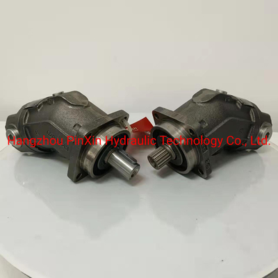
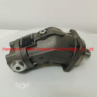
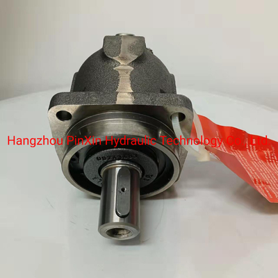
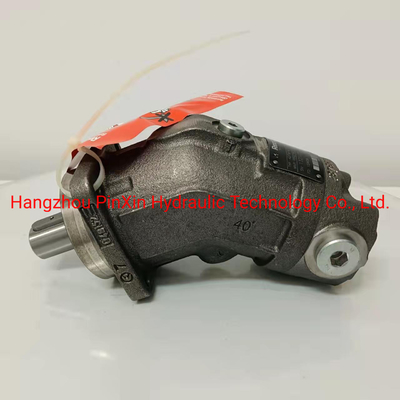
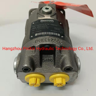
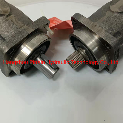
Hydraulic Motor A2FM Series Hydraulic Piston Motor
Supply models:
Hydraulic variable displacement axial motor A2FM10,A2FM12,A2FM16,A2FM23,A2FM28,A2FM32,A2FM45,A2FM56,A2FM63,A2FM80,A2FM90,A2FM107,A2FM125,A2FM160,A2FM180,A2FM200,A2FM250
Description:
Nominal pressure 400 bar
Peak pressure 450
The A2FM axial piston variable MOTOR in swash plate design for hydrostatic closed circuit transmissions
- Flow is proportional to drive speed and displacement and is infinitely variable
- Output flow increases with the swivel angle of the swash plate from 0 to its maximum value
- Flow direction changes smoothly when the swash plate is moved through the neutral position
- A wide range of highly adaptable control devices is available for different control and regulating functions
- The pump is equipped with two pressure-relief valves on the high pressure ports to protect the hydrostatic transmission (pump and motor) from overload
- The high-pressure relief valves also function as boost valves
- The integrated boost pump acts as a feed and control oil pump
- The maximum boost pressure is limited by a built-in boost pressure relief valve
- The integral pressure cut-off is standard
Our advantages:
1. There are lots of available A2FM series hydraulic piston motor in stock.
2. We are professional supplier of hydraulics.
3. Our factory has more than 10 years exprience in hydraulic industry.
4. Our factory is closed to Shanghai port & Ningbo port.
Real shooting:
We are offer these brand
We are offer the machines
Field application:
Package:
Delivery:
Payment term:
1. T/T: 30% deposit by T/T, 70% balance by T/T before shipment
2. L/C at sight
Trade term: EXW or FOB Ningbo/Shanghai
Delivery time:
We have huge quantity of inventory for complete pumps, motor and some spare parts,
so the leading time is within 3days if have in stock.
If haven't, within 5days if the quantity is less than 50pcs.
It depends on the quantity ordered.
Min. Order:
If the model is in common or the production are in our warehouse.
No MOQ for stocking production.Larger quantity, price will be more favorable.
Deliever Way:
By courier, like the DHL, UPS, Fedex,etc. It's door to door or barn to the door,
usually 5-7 days to arrive.
By air to air port, usually 3-5 days arrive.
By sea to sea port, usually 20-30 days arrive.
If your deliever time is very urgent, the best way is by courier or air.
If not, it's beat by sea.